The Asawari Mark IV was conceived after I crossed the Darbari milestone. That milestone taught me many things, which I could carry over into the Asawari range again, even though the Darbari was fundamentally a different animal -- it was a 3-way and had digital active crossovers. All the Asawaris are 2-way MTMs with passive crossovers.
From the Darbari, I learned about higher-order crossovers and the beauty of properly tamed metal cone drivers. I also grew fond of Dayton RS woofers and midbass drivers. Their price-performance ratio is unbeaten, and construction quality is superb. So I wanted to carry those lessons over into the next one or two Asawaris.
The Asawari Mark IV and Mark V were conceived of as twins. They were designed together, and there is not a millimetre of difference between the two enclosures in dimensions or construction, because the midbass drivers are almost identical in T/S parameters, and both use (different) tweeters with 100mm flanges (the common flange size for 1" domes).
Drivers
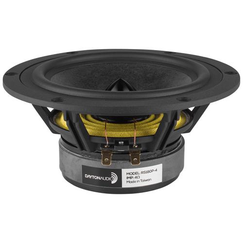
The Mark IV uses two Dayton RS180P-8 midbass drivers in parallel, and Tymphany XT25TG30-04 ring radiator tweeter. The combination was chosen to deliver very high quality on a reasonable budget. I didn't want a budget as tight as the first three Asawaris, but I did not want to get into Scan-Speak territory either.

The enclosure
The enclosure is straightforward, based on the basic data published by Jon Marsh about the Modula MTM maybe a decade ago, and similar conclusions reached by a lot of builders who built MTM designs around these drivers when they were new in the market. Basically, with a bass reflex design of about 30 litres of volume, and a port roughly 5" long and 2" in diameter, you can get a tuning in the mid-30s Hz and that makes for a decent bass response for this sort of MTM.
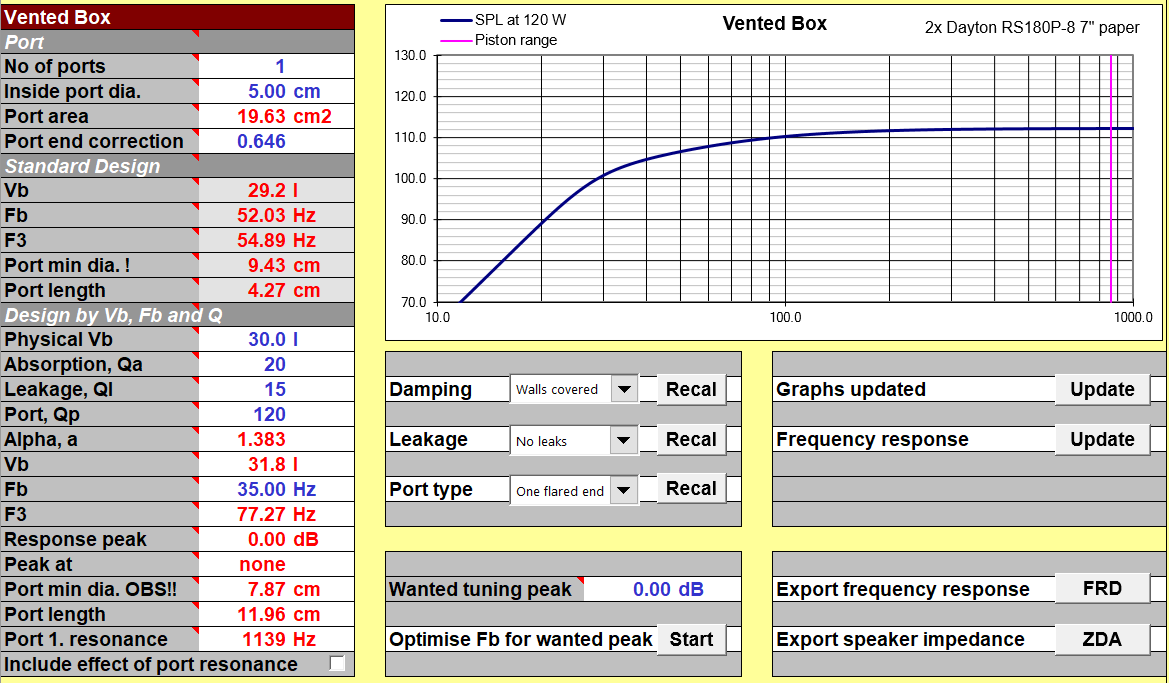
This Unibox screenshot show what I'm working with for the enclosure volume calculations. It's a 30 litre enclosure, the port diameter is 2" (see the "5 cm" in the top left of the image), and the port length too is given (see "11.96 cm") somewhere in the bottom left portion of the screenshot. The curve I am getting extends the low frequency response in a shallow curve for some distance, allowing the room modes to compensate for this slow fall with its own slow rise, thus (I hope) giving me fairly even in-room perceived bass response till about 30Hz or so.
I realised that 30 litres is too small to fill a floor-stander MTM. Therefore, I decided to partition the enclosure into two chambers, one with the drivers, and the second as a dead area at the bottom. This way, I got 30 litres behind the drivers even though the box had an overall volume of more like 45 litres.

All external surfaces are 25mm MDF, and all internal partitions and braces are 18-20mm commercial ply, a structure I have been following happily for some time now. The front baffle is made of two sheets of MDF, making a solid, vibration resistant, inert front baffle. The two sheets are joined together with Araldite to make them literally one solid block.

All braces are joined by inserting screws edgeways from outside, as well as Araldite. The screws are mandatory to pull the walls tight against the braces initially, when the Araldite is fresh. Once the Araldite sets, of course it has tremendous holding power. I have used just Araldite for fixing the braces, and it doesn't work, as happened with the Darbari. For some reason, I use stainless steel screws for my construction, because I don't want them to change due to ageing and rusting. (If you've ever removed an old, rusted, mild steel screw out of furniture, you'll understand my feeling.)

All braces are made out of 20mm plywood, as mentioned earlier.
The tweeter has a separate sealed chamber to protect it from the backwave of the midbass drivers, just in case that vibration results in any tiny vibration of the tweeter body and smudges the soundstage.
The photo below shows the internal bracing for the upper chamber ready and assembled, before being fitted inside the enclosure: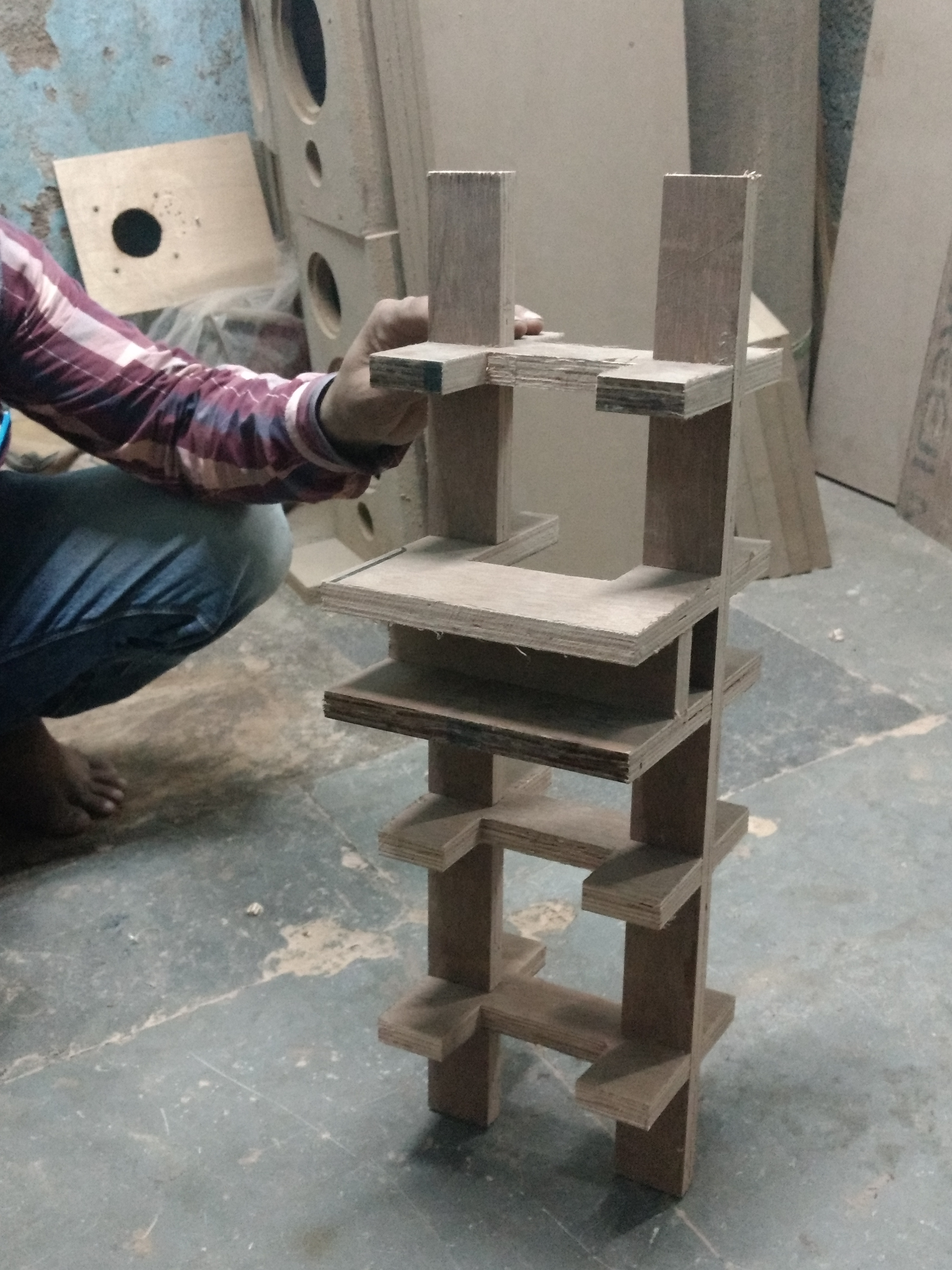
After fitting inside the enclosure, this is what it looks like:
In this photo, one can clearly see how the upper and lower chambers have been separated by two sheets of ply, with some half inch of gap between them, to guarantee that there is zero acoustic coupling between the two chambers. Only the upper chamber is used for the acoustic performance of the speaker; the lower chamber is purely as extra space for fitting additional crossover components if needed. One can also clearly see the tweeter chamber as an isolated chamber.
Below, one can see the enclosure finishing in progress. Sides have been clad in veneer, the front baffle is still a raw sheet of MDF. The front baffle is made of two sheets of MDF stuck in a sandwich, but the inner sheet is not visible here, its edge being covered in veneer. Only the outer sheet is visible, since its edges will get a roundover, hence the edge is exposed.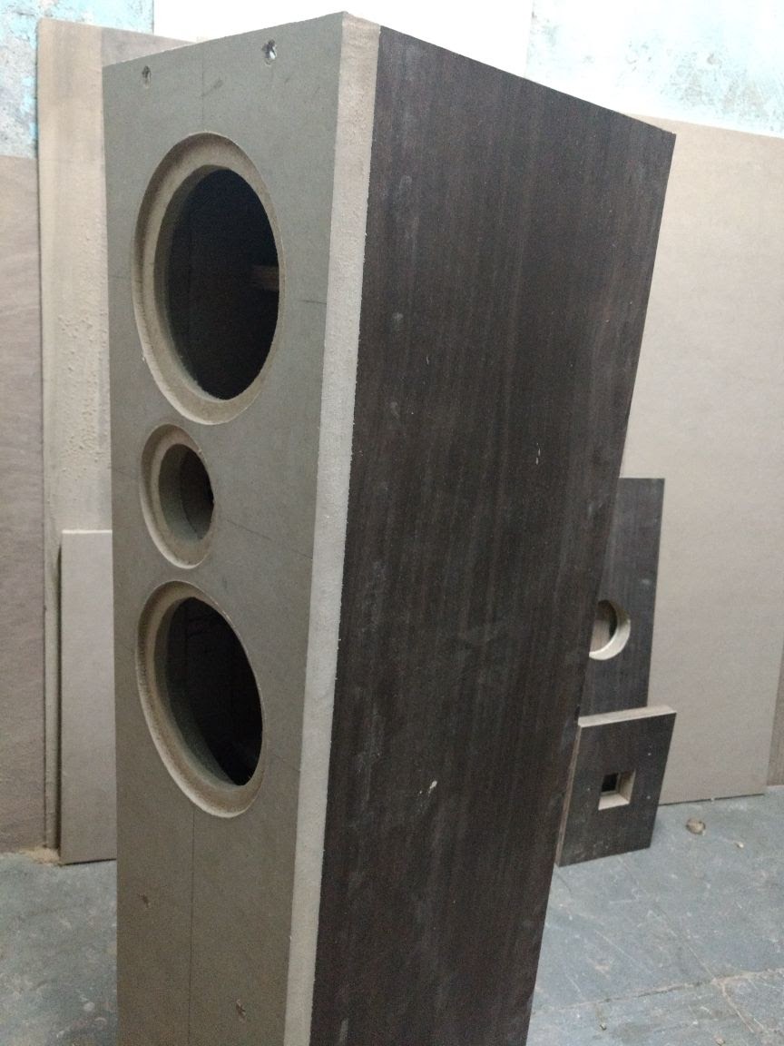
Below is the rear baffle, showing two removable pieces, with veneer applied to all surfaces:
Below is the same box in the same position, with the rear removable baffles removed, showing the internal bracing:
Next is a photo of the enclosures after the front baffle edge has been rounded over, and the polishing work is on in full swing. The front baffle has been coated with PU coloured black, and the rest of the surfaces have been left with transparent PU polish without any colour added, to allow the veneer to shine through:
The next photo is after polishing has been completed. The tops are showing raw MDF, which is intentional. They will be covered with precisely cut 6mm thick sheets of dark coloured glass, instead of veneer finish.
The completed enclosures: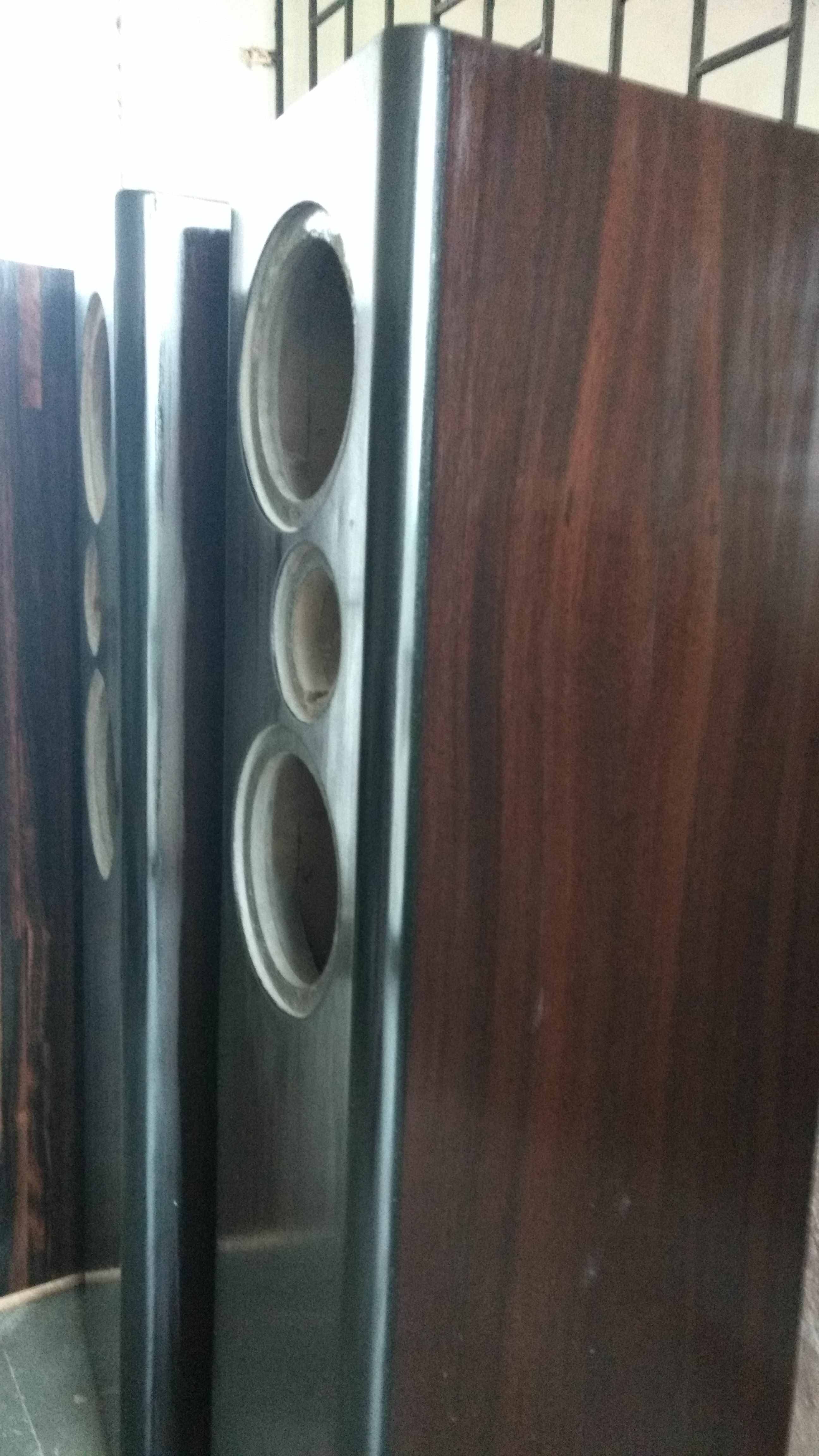
Below are the finished enclosures of the Asawari IV and V. The darker finish with the black front baffles are the Asawari IV, and the lighter, more eye-catching side walls and teakwood finish front baffles are of the Asawari V.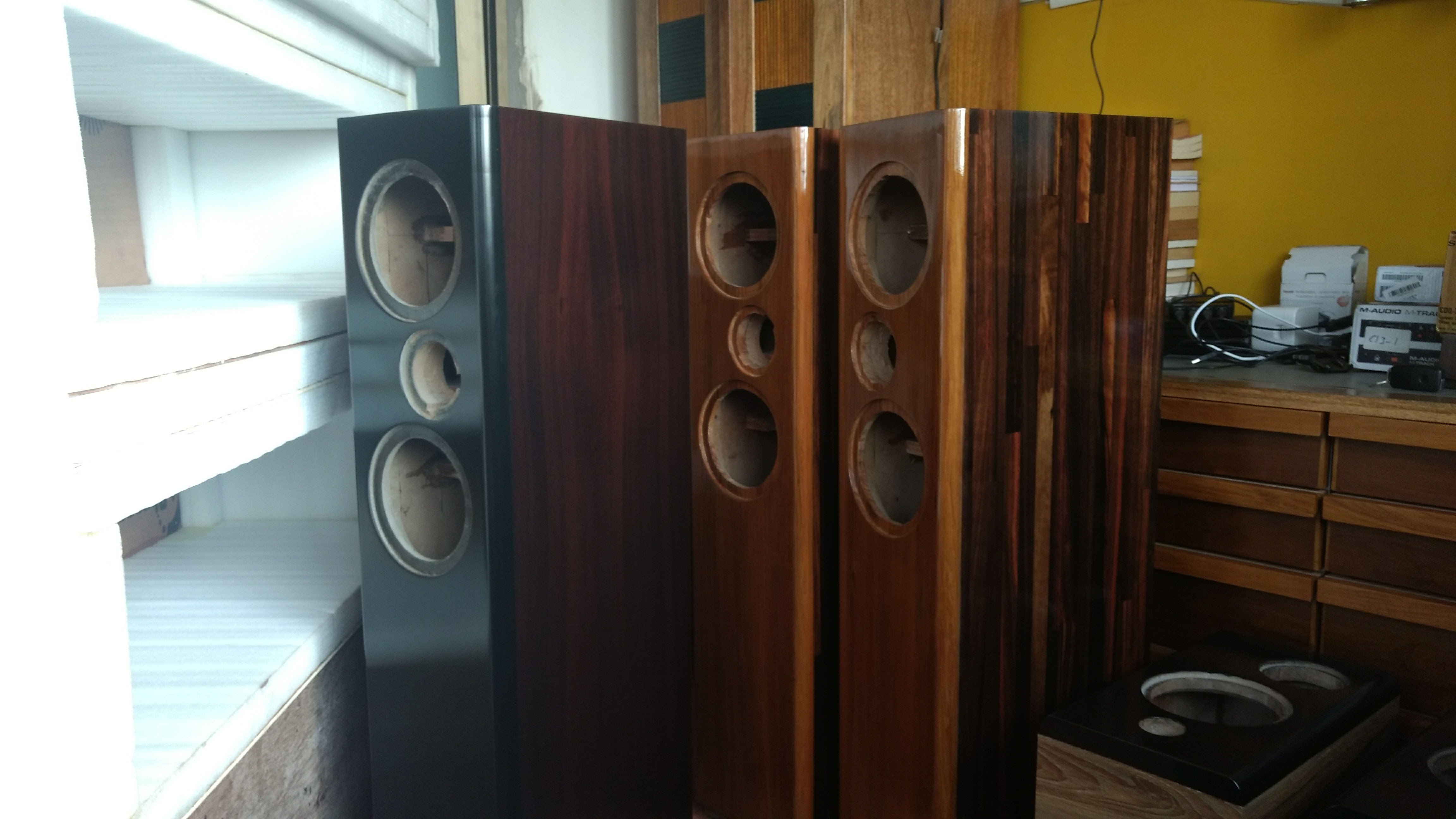
The video below shows the Asawari V in the first portion, and Asawari IV in the last portion.
The crossover
Crossover design starts by taking measurements of the drivers fitted to the enclosures. These were what the raw drivers looked like when measured. Note that these measures do not include anything meaningful below about 700-800Hz, since I only took gated farfield measurements, so that I could design the crossover.
I don't need to explain it, but the yellow line is the midbass driver SPL, and the green line is the tweeter SPL. The nasty cone breakup of the midbass starts before 4KHz, and peaks at about 5KHz. If that portion of the midbass output is remotely audible, it will colour the sound badly, so the aim of this crossover will be cut it as much as possible.
Out of this set of measurements came this crossover after much trial and error: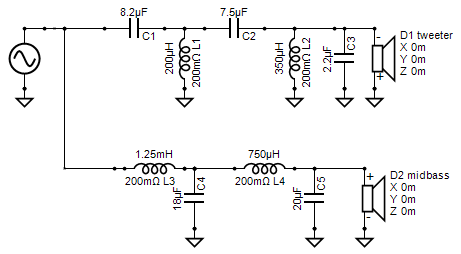
The capacitor C3 is there to cut the very top octave of the tweeter a bit. I started with nothing there, and wondered whether the slightly rising top end will cause trouble, so I added a 1uF, which cut the top octave a bit. I increased it to 2.2uF, purely based on the appearance of the curve, and left it there. What value do you need? It depends on whether you're listening on-axis or slightly off-axis, and on how sensitive your ears are to that octave. Most humans can't hear much in that octave. Some are very sensitive. And if you sit even 10 degrees off-axis, the SPL in that octave gets cut naturally anyway.
Otherwise it's a straightforward fourth-order electrical crossover.
This schematic gave the following final SPL curve: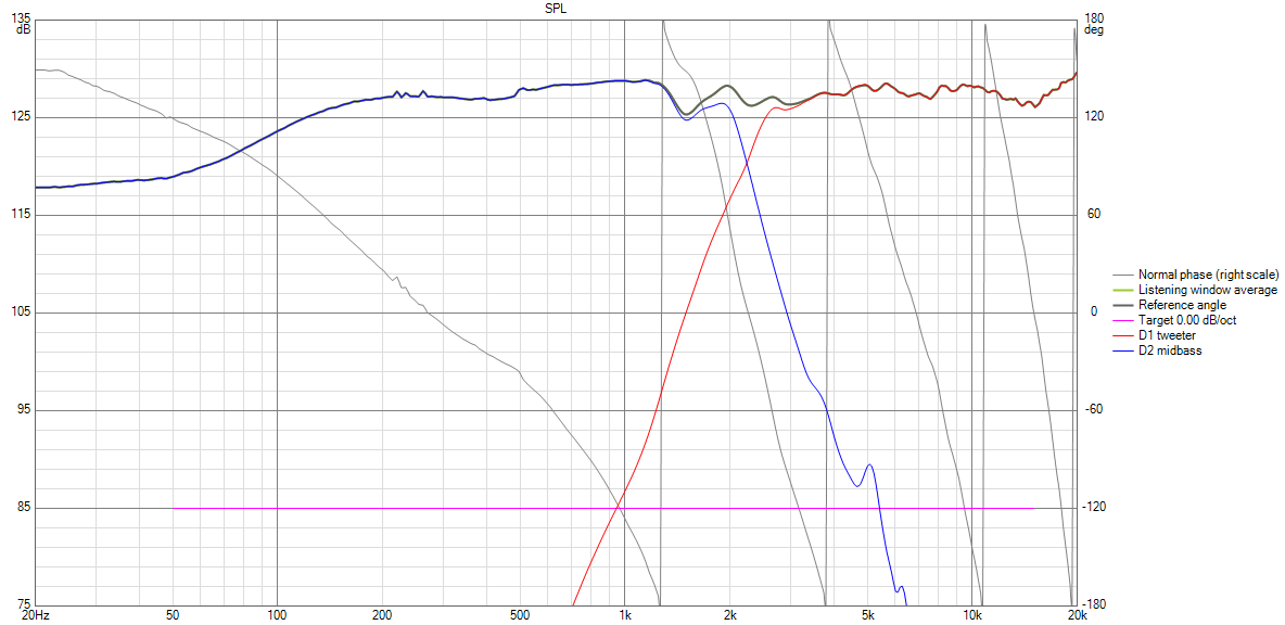
It's interesting to see where the 5KHz peak from the raw SPL curve has come. In the raw SPL curve above, the peak was very prominent and was far above the base SPL level. After the crossover, that has come down perhaps 40dB below the baseline. Maybe a steeper cut would have been better, but I have decided to leave it at this level unless listening sessions tell me further action is needed.
As one can see, the crossover point is about 2.2KHz.
And the impedance of this crossover is as shown: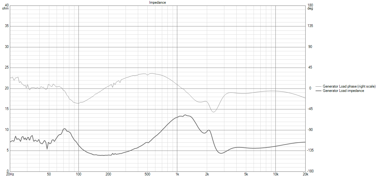
This is a solid 4 Ohm design, as was expected from the time I decided to choose two 8 Ohm midbass drivers and hook them up in parallel. Really low-power solid state amplifiers may not be able to drive this speaker to its best performance. As always, ignore everything in the impedance curve below about 100Hz, since the impedance measurement does not show what the reality will be. This impedance measurement was done before the bass reflex port was fitted and the enclosure filling was done. The final impedance at the low end will be impacted by all that.
Finalisation
Once the crossovers are assembled, the final sound needs to be tuned. This pair needed several weeks of tuning, done part-time and on weekends.
When the crossovers were put together and I started playing music, there were many things wrong with the sound.
- There was a strange droning resonance at one note, deep in the bass, whenever there was any such bass note in the music I was playing. In other words, there was some sort of bad resonance and standing wave which needed to be broken.
- At higher volumes, the sound became "shouty" and acquired a glare, as if the high frequencies were distorting or acquiring a disproportionate power of their own. The sound became unpleasant.
- The bass was really, really deep and resonant, as in, bass notes just wouldn't stop.
These were fixed by doing the following:
- I lined all the inner walls with this sound absorbent sheet available locally, sold by a brand called MMT Acoustix. It seems to work well.
- I added dacron wool inside, and tuned the quantity over a few iterations to get the sound right. Too much stuffing sucks the life out of the midrange, and too little stuffing brings the upper mids and treble too far forward. About four to five iterations got it right.
- I added baffle step compensation. An inductor of 0.6mH, in parallel with a 2-Ohm resistor, was added to the input lead upstream of the rest of the crossover. These values are expected to give you a 3dB step for a 4-Ohm speaker load. The baffle step compensation components are not shown in the crossover schematic above -- they were added later. You will have to add them too.
Now the speakers are sounding fine. There are dynamic, lively, but the mids and voices have a delicacy and warmth which wasn't there before. The bass has fallen into place. There is a lot of bass extension, without the resonating echo-chamber of boominess. The "shouty" sound is gone from the upper mids and highs. Even bright recordings ("Do you come from the land down under" by Men At Work) sound balanced without losing their edge.
I have a Chesky Audiophile Test CD, and it has some lovely drum solos recording in a quiet studio setting. The recording sounds very good.
This has turned out the best sounding Asawari so far. I am really glad.
Lessons learned
Some of these lessons will be applied immediately, in the next few weeks, to the Asawari 5 which is waiting for crossover assembly. That project should be fun.
- Be prepared to tune the bass by adding the right amount of stuffing in the right places to tame the standing waves, even though you can't eliminate them. Too much stuffing makes the bass reflex box into a sealed box and reduces the bass more than you'd like, and stuffing right behind the midbass drivers sucks the life out of the mids.
- Henceforth, I'll blindly line the enclosures with good sound absorbing sheets. Other than the one I used, the following two look very interesting too:
- pyramid-shapes in a sheet, 2" thick
- weird two-level shapes in a sheet, 2", apparently even more effective than the pyramid shapes
- I'll experiment with baffle step compensation. For average Indian rooms, a 6dB step may be too big, because we never really lose the low frequency waves totally -- they bounce back from the rear and side walls. So, I'll start with a 3dB step.
- The higher order crossover worked beautifully. There was no need for a 6th order or higher slope.
- Initially, I was thinking that I'd choose a different tweeter and bring down the Fc lower, maybe to 1.5 KHz or so, as I intend to try with the Asawari 5. But after prolonged listening sessions, I am quite happy with the 2.2KHz -- a lower Fc is not needed.
That's that, then. Now to sit back and enjoy the music.